FIELD FREE TIME OF FLIGHT (FFTOF)
Background
The Experimental Molecular Physics Research Group (former Section of Atomic Collisions) in ATOMKI has been studying the fragmentation of molecules by ion impact several decades ago. The earlier experimental techniques used electric or magnetic fields to separate fragment ions with different energies and fragment energy spectra of different molecules (some of with high biological or astrophysical relevance such as H2, H2O CH4 CO C6H6) were studied in the 2 to 2000 eV energy range. However, most of the fragments in such collision are emitted below 2 eV but this range could not be covered by this technique due to disturbances in the fields. Therefore, in 2018, we decided to develop an experimental setup allowing accurate measurement of the energy and angular distributions of low-energy fragment ions down to 0.1 eV emerging from ion–molecule collisions. In order to achieve this, the static magnetic and electric fields were minimized in our experimental chamber where the ion beam crossed the target gas jet and the and we use a position sensitive multi-channel plate (MCP) detector in the chamber to record the time of flight of freely moving fragment ions.
Key features of the FFTOF setup
Velocity range of detected fragment ions: 0.001 to 0.1 atomic unitscorresponding to 0.02 to 250 eV for H+
Angular range: 30° – 150°
Ion source: 14 GHz ECR, Energy 0.5 – 20*(Q) keV
Beam chopping: 100 ns – 10 us pulse, 1 – 20 kHz repetation rate
Detector: Quantar 3394A Ø 40 mm MCP 0.4 mm resolution, 16 ps time resolution
FFTOF Chamber: HV compatible, base pressure: 5 x 10⁻⁷ mbar
Vacuum system: 400 l/s turbomolecular pump + scroll
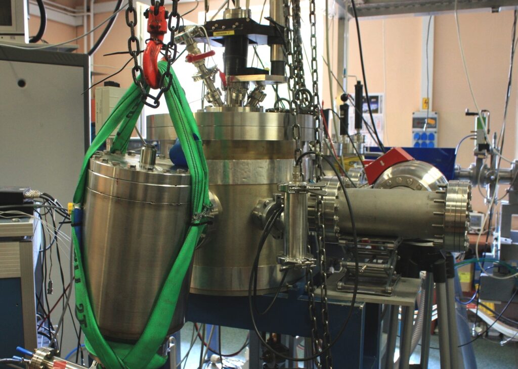
Introduction of the FFTOF setup
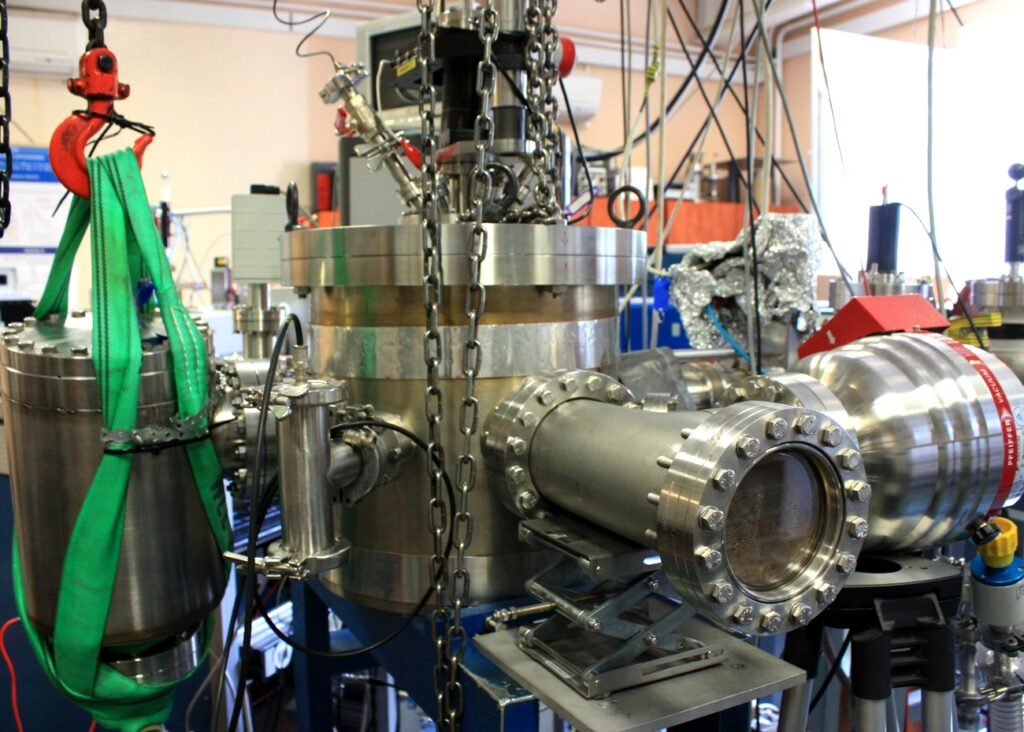
The experimental arrangement allows accurate measurement of the velocity distribution of ionic fragments from ion-impacted molecules in the low to intermediate velocity range (10⁻³–0.1 atomic units, corresponding to 0.02–250 eV for H⁺) and over a wide angular range (30–150°). To achieve this, static magnetic and electric fields were minimized in the interaction chamber where the ion beam intersects the target gas jet. A double μ-metal shield reduced the magnetic field to a maximum of 40 mG. To ensure near-zero electric field conditions, all insulating surfaces were shielded with metal screens, and chamber components were manufactured from copper whenever possible to avoid contact potential differences. Surfaces directly exposed to the ion beam or fragment ions were coated with gold. Since gold and copper have identical contact potentials, and the contact potential of iron differs by only 0.06 V, the effect of the μ-metal shield on the electric field is expected to be negligible.
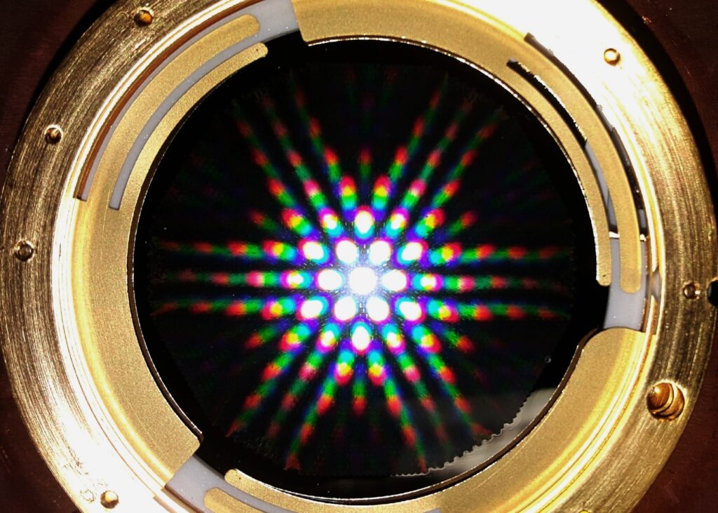
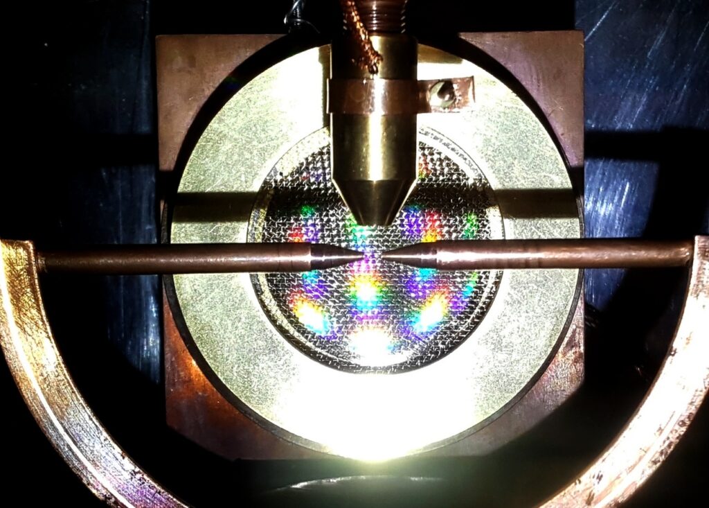
The fragment ions can fly freely from the center to the first covering grid of the position sensitive microchannel plate (MCP) detector. The detector with nominal diameter of 40 mm is located on a rotatable table coaxial with the chamber in order to set the detector at different angles with respect to the beam. The detector can view angular range of -14° to +14° with respect to the center line. In order to avoid fragments collected from the background gases, the beam was guided through a narrow copper tube of 5 mm diameter in the chamber with a gap of 2 cm in the center. This gap was further narrowed to 3 mm by a pair of conic tubes with inner diameters of 0.75 mm at the ends. The current of the beam guided through the tube was measured by a Faraday cup at the end and the current falling on the tube was also measured. Typical currents for chopped beams are 1 pA in the Faraday cup and 0.2 pA on the tube, which indicates that the beam can be well guided through and only negligible part touched the tube.
Beams of various singly and multiply charged atomic and molecular ions (e.g., H, O, H₂, H₃, He, OH, Ne, S, Xe) are produced by an Electron Cyclotron Resonance Ion Source (ECRIS). To measure the flight time of fragment ions from the target molecules, the primary beam was pulsed using a parallel-plate electrostatic deflector placed 117 cm upstream from the collision center. The beam is collimated by two 0.5 mm diaphragms separated by 20 cm at the chamber entrance.
The collimated beam intersects an effusive molecular gas jet (e.g., H₂, O₂, CO, CH₄) at the chamber center. The jet can be cooled with liquid nitrogen supplied to the effusive nozzle, whose temperature is monitored by a thermocouple and can reach 120 K. The nozzle position relative to the beam axis can be adjusted to vary the target density and velocity spread. Gas impurities are monitored with a quadrupole mass spectrometer (QMS).
If you would like to learn more about the ICA setup, please refer to the following publication: